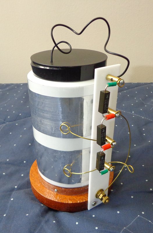
In January 2015 I built a new device based
on the
electronic version of Bennet's doubler,
using a tubular construction. It was made from a section of a PET bottle,
a large PEAD pot that fits inside it precisely, thick aluminum foil, some
hardware and three microwave oven diodes.
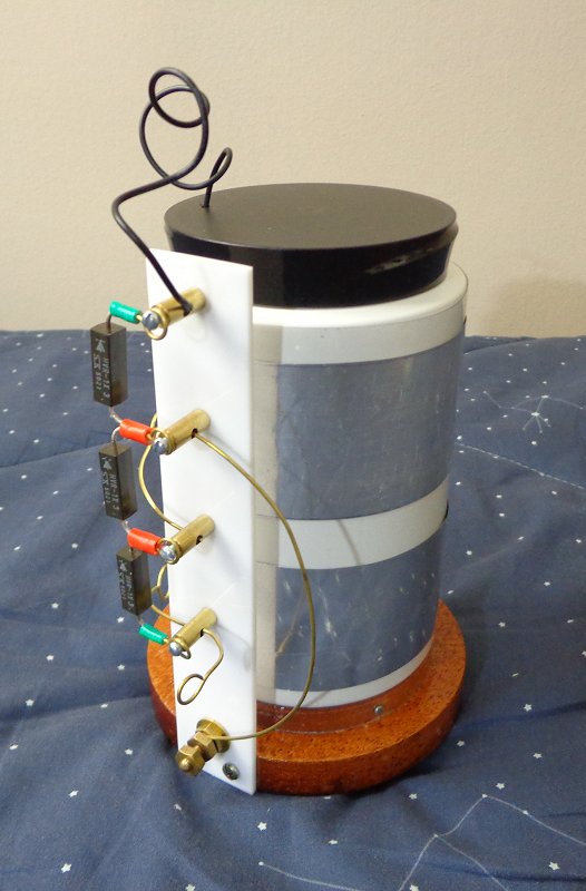
The external tube is fixed over a wood
base with three little screws. The base has a hole in the center to let
the air escape, and three rubber supports. Two aluminum foil cylinders are
fixed on it, with adhesive tape. The inner pot has a similar cylinder
inside it, aligned with the lower external cylinder when the pot is
entirely inside the outer tube. A flexible wire connects the inner
cylinder with the terminal at the top. Three high-voltage diodes are
mounted as shown in an acrylic plate, contacting, from top to bottom, the
inner cylinder, the ground terminal, the upper external cylinder, and the
lower external cylinder. The diodes can be easily reversed, by connecting
the entire string backwards. The main output is the lower external
cylinder, connected to a simple terminal with a wire ring. The ground
connection can be just a chain going to a partially conductive surface
where the machine is supported. As the supports of the base are insulating
(the ground terminal actually is not in contact with the base, but close
to it) the output and ground connections can be reversed if convenient.
The machine is operated by raising the internal pot until the internal
cylinder is aligned with the upper external cylinder and lowering it
again, repeating the operation in rapid succession. With the diodes as
shown, with the cathodes pointing up, the machine generates negative
output. With the diodes reversed, the output is positive.
The machine, starting completely discharged, starts easily, probably
helped by triboelectric charges generated by the rubbing of the pot and
the tube. When the pot is raised, the output voltage climbs to
successively higher levels at each cycle, saturating at about 10 kV,
limited essentially by the breakdown voltage of the lower diode. A
high-voltage capacitor connected across the output is easily charged.
As the polarities of the plates do not change, however, soon charges
accumulate at the bare plastic surfaces opposite to the plates, and the
machine ceases to operate. It's then seen that the movement does not
increase the output voltage significantly, or that the output voltage
rises when the pot is lowered instead of when it is raised. The normal
operation can then be restored by inverting the diodes, with opposite
polarities.

Operation
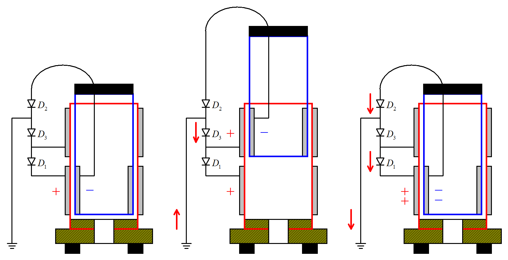
The ideal operation of the doubler is
as in the diagram above. Starting with the lower external plate and
the internal plate oppositely charged as shown, when the pot is raised
positive charges are attracted from the ground through D3,
charging the upper plate with a copy of the charge in the lower plate.
When the pot is lowered, the charge in the upper plate adds to the
charge in the lower plate through D1, while the
charge in the internal plate is doubled too through D2
and the ground. In practice the doubling is not complete due to stray
capacitances and leakage.


