 The operation of the machine as a doubler is
as follows:
The operation of the machine as a doubler is
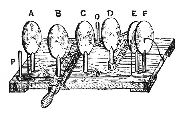
as follows:With all the plates discharged, an initial charge +Q (positive for example) is applied to plate A. The lever handle is then moved to the left, grounding plate B in post P close to plate A. At the same time, the other linked lever makes plate D touch plate E, and any charges on plates D and E move to plate A trough the wire W, attracted by the grounded plate B. Plate B receives then an opposite charge -Q. The lever handle is then moved to the right, causing plate B to touch plate C and the linked lever to ground plate D in post Q close to plate C. The charge in plate B moves to plate C, and an inverted copy +Q is generated in plate D. With the return of the lever to the left, the charge in plate D is transferred to plate A, doubling the charge there to +2Q, and generating -2Q in plate B. In the next cycle the charge in plate A becomes +5Q. The charge in plate C increases in proportion, becoming -Q in the first cycle, -3Q in the second, -8Q in the third, and so on.
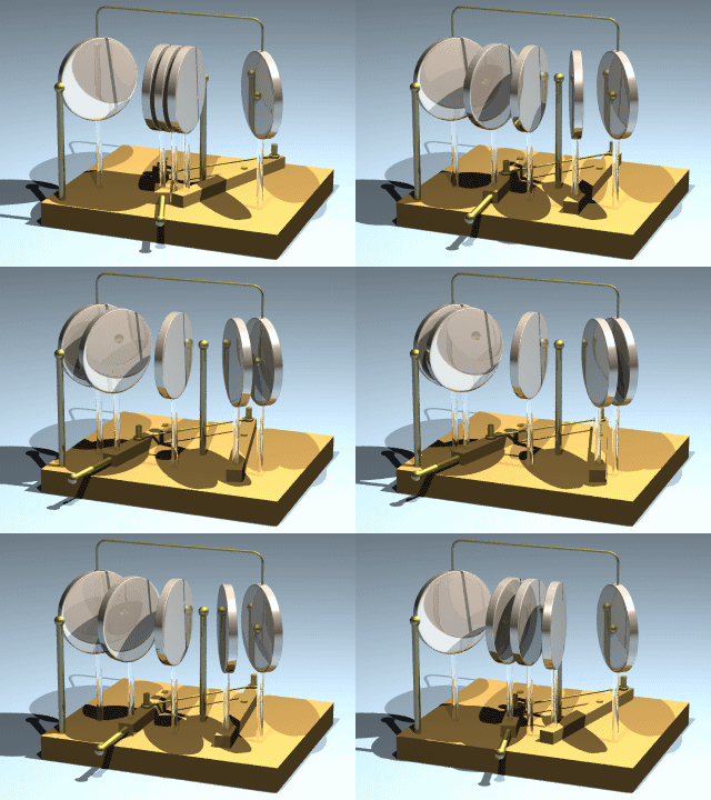
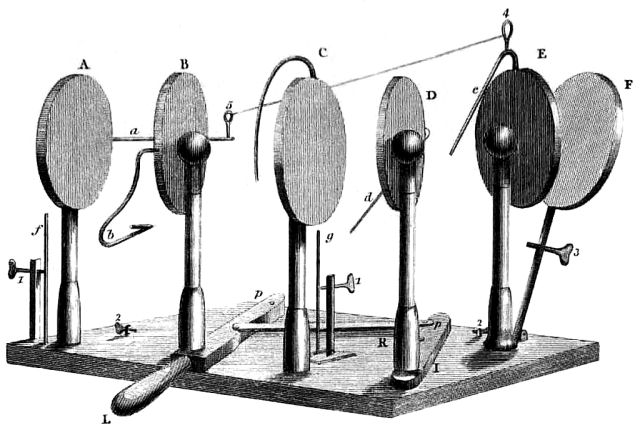
In February 2007, I built a machine, trying to interpret the original picture. The reciprocating levers and the correct position of the plates I figured out as in the animation and the photos below. The levers are an interesting mechanical solution, causing plate D to move in a nonlinear relation to plate B, but that puts them in symmetrical positions at the two extremes of the movement. The plates A and E must be mounted at an angle with the central plate and slightly misaligned with it, in order to be parallel with the moving plates when they are close to them. Note that the post Q isn't behind the bar interconnecting the levers, as in the original picture. I omitted plate F, that just increases the capacitance of the pair A-E if grounded, and placed the wire W above the plates for better insulation. I also added spark shields to plates A and C, otherwise they easily discharge to the grounding posts.
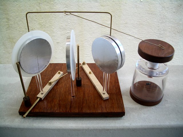
The plates were made with wood, polished and covered with adhesive aluminum tape. They have 8 cm of diameter. The supports are 5 mm acrylic rods. In the pictures, the machine is shown connected to an electroscope.
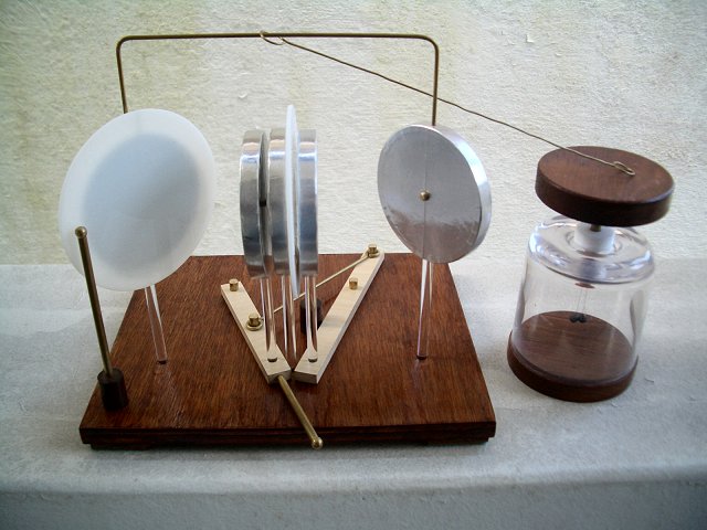
The machine self-excites easily, and reaches a maximum of about 15 kV in plates A-E and C, with opposite polarities. Enough for audible and visible little sparks if the plates are touched. It probably can reach greater voltages with spark shields added to plates B and D too, facing the spark shields already mounted, but this would impede the connections to the grounding posts, and the mechanical solution would have to be changed.
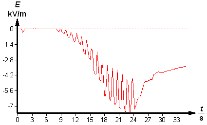
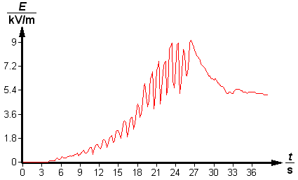
The curves below show measurements of the output voltage of the machine in plate E, using a PHYWE electric field meter placed a few cm away from the plate. The distance was calibrated so the reading in Volts/meter corresponds to the potential at the plate in Volts. It can be seen how the voltage increases from cycle to cycle. The maximum voltages are obtained when the movable plates are at the center, and the minimum when they are at the sides. The voltage quickly drops after the movement stops, and doesn't reach more than 9 kV due to leakage in the insulation (the machine was not very clean). The growth rate of the voltage is smaller that the ideal due to losses and the interconnection between plates A and E, that divides the charge between them when the moving plates are at the center. Negative and positive charging is shown.
This machine is interesting because it is exactly equivalent to symmetrical rotating machines developed much later. The plates A and C accumulate opposite charges transported by the moving plates B and D and serve also as electric inductors when the same moving plates are close to them and grounded by the "neutralizer" contacts P and Q. It is evident that the two moving plates can be monted on rotating supports, and plates A and E reduced to a single plate. If two supports are used, the machine is equivalent to the symmetrical Toepler machine. If just one rotating support is used, it is equivalent to Belli's machine, Lord Kelvin's replenisher, Lebiez machine, or the Dirod machine. Plate C could be omitted, and plate B used directly to induce charge on plate D when it is grounded. The machine in this form operates exactly as Bennet's doubler. If rotating disks are used instead of the moving plates, the construction is equivalent to the rotating Bennet's doubler described here. The comparison with Belli's machine is not exact, however, because that machine relies on envolving the charge carriers with the collector structures to extract the charge in the carriers, while Wilson's machine relies on charge transport to the large capacitances formed between plates A-B and C-D to extract the charges from the carriers D and B respectively, and the extractions are done alternately, not simultaneously as in Belli's machine. The same happens with the replenisher.
The machine can also be used as Cavallo's multiplier, by removing the link between the two levers. Plate D is moved to the left, and an initial charge in plates A-E can be multiplied in plate C by successive back-and-forth movements of the main lever. The opposite voltages generated in plates C and D can then be increased by moving plate D away from plate C. Similar operation can be done with the initial charge in plate C, plate B moved to the left, and back-and-forth movements of the linked lever generating multiplied opposite charges in plates E-A and B. With the wire W removed, the machine is a cascade of two Cavallo's multipliers, with the extra plate F forming the final storage capacitor.
The original picture, in [p109] is more elaborated, showing position adjustments 1-3, and the plates secured from behind in the insulating posts. The feedback connection between plates A and E is a suspended wire.
An interesting note about the construction of the machine: The plates were made as wood disks covered with aluminum tape, and borders of the tape were exposed at the edges of the disks. No serious problem, but the tape has a glue that never dries. The exposed borders were always attracting dust, and the dust was getting fixed there due to the glue, forming points that were causing losses through corona. An effective fix for the problem was to apply a thin layer of shellac varnish to the edges of the disks, covering the exposed tape borders.
A video of the machine in operation.
Another video, showing a machine that is Wilson's machine with a symmetrical mechanical construction.
A copy of the original paper by Wilson.