Electrostatic
measurements
In this page I will
describe some
experiments about high-voltage measurements in my electrostatic
machines and other devices, using measuring instruments built by me.
Initially I describe a spark gap voltmeter, Henley's electrometer,
and a pith ball electroscope and
comment on how to calibrate the meters for more precise measurements.
Sphere gap
meter
Uniform field spark gap
Spark gaps formed by parallel plates, dimensioned so the field at the
center of the plates is approximately uniform and maximum, spark when
the electric field at the gap is close to 30 kV/cm, in normal
atmospheric conditions. In [2] there is a long discussion about
behavior of spark gaps, with formulas due to various researchers that
approximate the breakdown voltage as function of the gap spacing. It's
well known also that the air pressure and temperature affect the
breakdown voltage. Another effect is that the electric field required
for breakdown in small gaps is larger than in the case of large gaps.
From the discussion there, a good formula for this case, which also
appears in [3], can be:
V is the
breakdown in kV,
d
the gap space in cm, and
δ
is a correction factor
for pressure and temperature, with
p
the pressure in torr (mm Hg) and
T
the temperature in degrees Celsius. It reduces to 1 at sea level and 20
°C:
Sphere spark gap
A classical method for
high-voltage
measurement is a sphere spark gap, also object of many studies in the
past, as it was for long time the most practical way to measure high
voltages. Several formulas and tables for the relation between
the geometry of the system and the sparking voltage can be found. This
measuring method is considered precise within a few per cent, if enough
care is taken. I found convenient to use the formulas that can be found
in reference [1] (the first appears in [3] and [6] too, and comes from
[7] ). For two balls, not
grounded (symmetrically charged to
±
V/2),
the breakdown voltage is:

where V is in
kV, d
is the gap distance in cm, R
is the radius of the spheres, and E
is
the electric field at the surface or one sphere that causes breakdown
(V/cm).
The value of E
is around
30 kV/cm in air, but it varies with the geometry, pressure, and
temperature. A better expression for E for a sphere gap
is (kV/cm):
The correction term δ
is the same listed above. The formula for V is an
approximation, since there is no simple
solution for the electric field on a two-spheres configuration. The
exact value can be calculated by a series, however, and is very close
to
this approximation. The second formula says that the breakdown field
depends on
the radius of the spheres, and is an empirical simplification
of
the quite complicated exact behavior of a sphere spark gap.
In [1] there is also a formula for the case of one grounded sphere,
which
the author says that does not work well due to interference of the
supports of the spheres, greater in this case. Really, the formula
predicts values a bit smaller than the correct values from the exact
solution even between two ideal spheres.

The first formula gives a value of V = dE when R>>d and V = 2RE when d>>R, meaning that
both spheres start to produce corona. The last formula also gives V = dE in the first
case, but gives V = dR
in the last, meaning that just one sphere produces corona.
I
made a sphere gap with two 3.4 cm hollow copper spheres mounted on a
support
where
their separation can be varied and measured by a ruler. Spheres of
other sizes, the same that I use for terminals of electrostatic
machines, can be used too. The
system used, supporting the balls in parallel insulators, is
not
the best
because the supports interfere in the electric field shaping for long
sparks and even produce some corona, but I found that at least up to 25
kV the gap meter as built works correctly. A more precise distance
meter could be used too, as the simple ruler gives a precision of 0.25
mm
at most. In the picture above, the device can be seen, connected in
parallel with a Leyden jar and an insulated Henley electrometer. The
connections are not critical, and wires with loops at the ends and a
ball chain are enough. One ball is grounded at the wooden table and
the other connected to the device to be measured, which in that case
was
a small electrostatic machine.
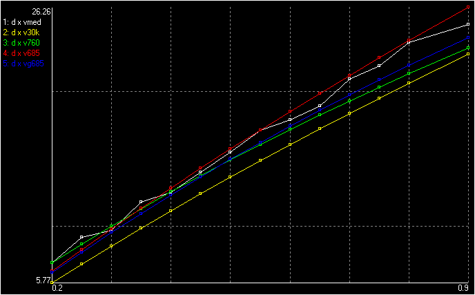
The curves below show a comparison between these formulas and my
measurements, for T
= 26 °C and p
= 685 mm Hg, for distances d
between 0.2 and 0.9 cm, with the vertical scale in kV. "vmed" are the
experimental values. "v30k" the values assuming E
= 30 kV/cm, "v760" the values assuming 20 °C and 760 mm Hg,
"v685" the values for the experimental conditions, and "vg685" the
corresponding values using the formula for one grounded sphere. Most of
the
experimental values are between the two last
curves,
as they should be.
 Sphere gap
measurements and calculations
This video shows
the system shown in the photo above in operation.
Henley's quadrant
electrometer
Henley's
electrometer
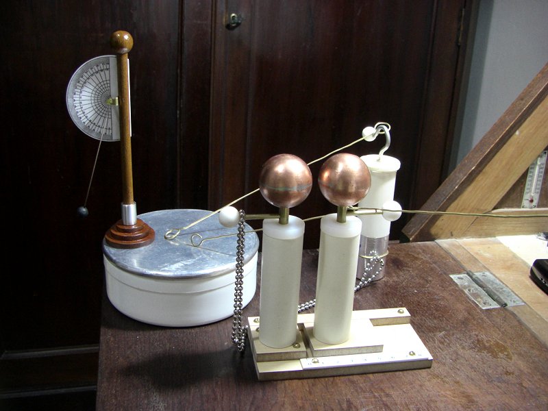
[4] is a simple repulsion electrometer. It has a
wooden rod with a ball at the top and a metal ferrule at the bottom,
which has a pin that can be fixed on a base or on other devices. A
light
ball is suspended at the center of an angular scale through a
light stick. When connected to high voltage, the ball is
repelled
from
the vertical support, and the angle is a measurement of the voltage. I
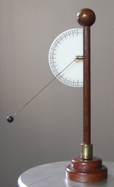
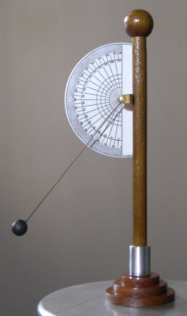
made several, some of them shown above. The first is smaller and more
sensitive. The second has a guard to reduce the effect of the scale
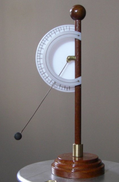
repelling or attracting the index [5]. The third has a
better
support for
the index, more similar to the system used in the old instruments
and that allows free movement even with the repulsion between the scale
and the index. The index was fixed in a hole in a short brass cylinder
with point bearings at both ends, one of them in a screw fixed to the
center of the scale, allowing pressure ajdustment. The balls were made
of plastic foam, painted with
conductive ink. The index sticks were made from vegetal fibers used in
brooms.
These meters are not very precise, as the indication depends on the
surroundings since they are not shielded. The size of the suspended
ball essentially determines the
maximum
voltage that can be measured without losses, as it is there that the
charge concentration is more intense, and it starts to produce
corona when the voltage is greater than about 30 kV divided by the
radius of the ball in cm. But they continue to work after this point,
since the materials used have high resistivity.
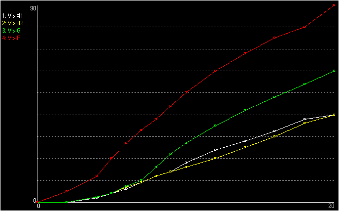
With the devices placed at the edge of a charged conductive plate, I
get, for 20 kV, 90°, 60°, and 40° for the three
electrometers shown, with suspended balls progressively larger. The
angle initially rises in a very nonlinear way, probably effect of the
base, and then becomes
approximately
directly proportional to the voltage, as shown below. This same effect
was observed with the old electrometers too and was mentioned by Volta.
The curve "P" is
for the smallest electrometer, "G" for the one with guard, and #1 and
#2 for two copies of the third, which should be identical but show a
small difference.
 Angle x
voltage (kV) for the Henley electrometers.
Pith ball electroscope
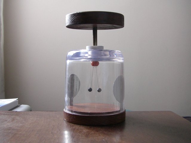
Ball electroscope
This simple electroscope
uses two
plastic foam balls painted with conductive ink suspended by thin wires
in an inverted acrylic cup mounted over a wood base. The upper terminal
passes through a Teflon insulator in a hole in the cup, for better
insulation. Two disks of adhesive aluminum foil are pasted on the
interior walls of the pot and connected with the base. The top plate is
made of wood. This electroscope was made as part of a "
doubler of
electricity", but is very useful alone. The balls separate
with ~500 V,
and almost touch the metal plates with ~5000 V. The
separation of
the
balls as function of the voltage is, approximately:
0.5 kV 0+ mm
1.0 kV 3 mm
2.0 kV 8 mm
3.0 kV 15 mm
4.0 kV 20 mm
5.0 kV Saturation
This the correct form of
making a
pith ball electroscope, although with modern materials, much as they
were when
used
extensively in the early studies about electricity in the XVIII
century. Better variations were the gold-leaf electroscope, invented by
Bennet, where two
strips of very thin gold leaf were used, that was very sensitive, and
the straw electrometer, used by Volta, where two straw strips were
used. The two metal
strips and the conductive base are necessary, or charge
accumulates on the inner walls of the cup and the balls don't close
when the device is discharged. They also provide shielding from
external interferences. Many modern texts show electroscopes
made with a strip of aluminum foil folded over a wire inside a glass
bottle. This is incorrect, and would result in a very poor instrument.
Calibration
The electrometers and
electroscopes can
be calibrated
using the spark gap, with the setup shown in the first photo, but
for verification I made a 200 MΩ
resistor with 20 10-MΩ resistors connected in series, and
used it in
series with a microamperimeter to directly measure a test voltage,
generated by a flyback-based high-voltage power supply. This method has
its problems, because so high resistance is sensitive to any
minimum leakage, even through the leads of the meter (when measuring
the resistance) touching anything.
At 20 kV there is 1000 V over each resistor (0.1 W), and they may leak
or become nonlinear in this condition. The high-voltage end of the
resistor string produces some corona too. I mounted the
resistors
over an acrylic plate strip with holes in a zigzag pattern and inserted
the strip
in a section of 3/4" PVC tube, with terminals at the ends for
connections. The precision of the completed assembly is expected to be
better than the 5% of the individual resistors, 5/√20
= 1.1%, but the actual measured value varies, depending on
humidity and even on how the
leads of the meter are positioned. It's better to measure all the
resistors separately and add the values. Another inconvenience is that
at 20
kV the resistor consumes 100 µA, a too high current for an
electrostatic machine. This measurement method can then be used only to
calibrate other methods.
A field-mill electric field meter can also be used. The meter
is
mounted at some distance from an insulated sphere, and the sphere is
connected to a known low voltage with the meter in its lower range. The
distance is then adjusted until an electric field with a chosen
proportion to the voltage is obtained. The scale multiplier of the
meter is then changed to the maximum range and high-voltage
measurements can be made. For example, the sphere is connected to 15 V
and the meter is adjusted to read 150 V/m at the 1 kV/m range. At the
100 kV/m range the meter reads 15 kV/m with 1.5 kV in the sphere. The
problem with this system is that any high voltage present in the
surroundings affects the calibration at low voltage. If the sphere is
first connected to high voltage (even days before), the insulator
holding it holds charge
for some time, and a subsequent calibration at low voltage is affected.
It's necessary to use a partially conductive support for the sphere, or
to use a grounded shield around the meter and the
sphere, a Faraday cage, what complicates the assembly. The calibration
can of course be done without these problems by comparison with the
resistor method, at high voltage, but then the precision of the first
method must be asserted. Note also that
the meter saturates with just 10 kV. For greater range the sphere and
the meter must be quite far from each other, and calibration is more
difficult, requiring greater voltage and more care with stray charges
and shielding.
Some theory
Calculation of the
expected reading for
a given voltage is possible, but
the exact solution is a three-dimensions electrostatics problem. The
case of the ball
electroscope is well known, although without taking the metal plates or
suspending wires in consideration. The case of Henley's electrometer is
more complex, because the ball is repelled by a more complicated
structure.
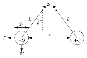
For two spheres, the angle θ
with the vertical line follows the relation
F/
W = tan
θ, with
F
being the electrical force in a sphere and
W
its weight, or gravitational force, ignoring the suspending lines. For
Henley's electrometer the relation is approximately valid too,
supposing that the electrical force on the sphere is horizontal. Some
old instruments were graduated with tangent scales due to this [5]. The
relation between the electrical force and the voltage, however, is not
linear. For the pith-ball electrometer the charge in one of the balls
can be easily found, assuming that the balls behave as a point charges
at their centers and ignoring the suspension lines and surroundings:
where
m
is the mass of a ball,
r
the radius
, x
their separation,
L
the length of the suspension lines (to the centers of the balls),
g = gravity
acceleration, 9.8 m/s
2, and
k the Coulomb
constant 9 ×10
9 Nm
2/C
2
(1/(4πε
0) exactly, with
ε
0 being the electric constant
= :8.85419 × 10
-12 F/m). The voltage can
be found by treating the two balls as a
distributed
capacitor with
capacitance
C
and charge 2
Q,
resulting in
V = 2
Q/
C. The capacitance
C varies between the capacitance
of two spheres in contact, 8πε
0rLn2 = 8πε
0r × 0.69315, and the capacitance of two spheres far apart, 8πε
0r. A simple approximation, with precise values for
x
= 0,
x = 2
r, and
x =
∞, resulting in
A
= 2.50092 and
B
= 3.60806 (or, as in [6],
A
= 2 and
B
= 3), is:
Instead of first finding
Q
and then
V,
the force can be found directly from the capacitance and the voltage as
the derivative of the stored energy in relation to the separation of
the spheres:
And then, as
F
=
mg tan
θ, a better approximation is found:
With
A = 2 and
B = 3 this formula gives the same result obtained by finding
Q from the point charges approximation first, and works well for large distances. The exact charge, capacitance, and force
can be found by series [6]. The calculations agree with
experiments only approximately, because there is
significant weight in the suspension lines (easy to take into account
if the lines are rigid by adding
mline/2
to
m),
some charge too (very little), and specially because the metal
plates in
the walls of the electroscope and the bottom plate attract the
balls. For two balls far from other objects the approximation is very
good, however. For example, with two 1.5-cm plastic foam balls painted
with conductive ink,
m
= 0.0004 kg,
r
=
0.0075 m, hanging with
L
= 0.131 m from thin lines, with
V
= 5 kV the separation is found experimentally as 9 mm (0.009 m). The
last formula
above gives
V =
5.03 kV.
Old instruments
Volta's instruments
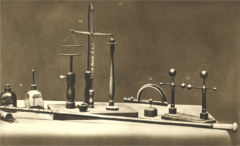
The picture above shows some measurement instruments used by Alessandro
Volta. A pith ball electroscope, an electric force balance, Henley's
electrometer with a guard ring, and a spark gap.
[1] F. W. Peek, "Dielectric phenomena in high-voltage engineering,"
McGraw-Hill, 1915.
[2] J. M. Meek and J. D. Craggs, "Electrical breakdown of gases,"
Oxford, 1953.
[3] M. S. Naidu and V. Kamaraju, "High voltage engineering",
McGraw-Hill, 1995.
[4] J. Priestley, "An account or a new electrometer, contrived by Mr.
William Henly, and of several Electrical Experiments made by him, in a
Letter from Dr. Priestley, F. R. S. to Dr. Franklin, F. R.
S.,"
Philosophical Transactions, 62, 1772, p. 359-364.
[5] See "Electricity", Encyclopaedia Britannica, 1823.
[6] A. Russel, "The electrostatic problem of two conducting spheres,"
Journal of the IEE, Vol. 65, 365, pp. 517-535, May 1927.
[7] G. R. Dean, "The maximum voltage gradient in a spark gap in terms
of the radius of curvature of the electrodes," General Electric Review,
Vol. 16, pp. 148-150, 1913.
Created: 26/1/2012
Last update: 20/2/2012
By Antonio Carlos M. de Queiroz
Return to Electrostatic
Machines.
